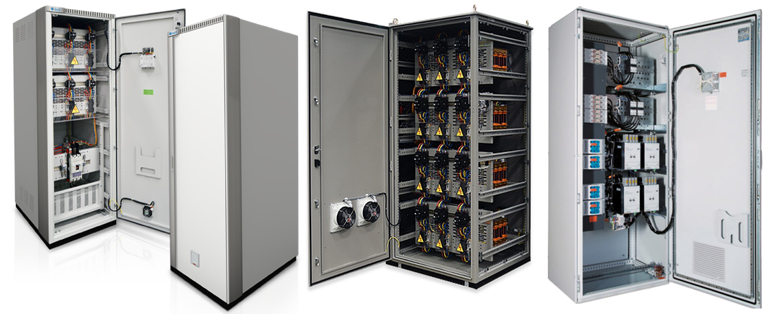
TECHNICAL DATA
Reactive Power(KVAr): 1600KVAr
Rated Voltage(V): From 380 up to 525V
Rated Insulation Voltage(kV): 800V
Rated Impulse withstand Voltage: Up to 6kV
Rated Frequency: Up to 60Hz
Busbar Type: Pure Copper Bars, with 99,9% conductivity
Rated Current for Main Distribution Busbar(A): Up to 1600A
Conditional Short Circuit Current: 50kA
Rated Short-time withstand Current: 50kA @ 1sec
Incoming Feeders: Up to 2500A
Form of Separation: Up to 3a
Ventilation: Natural
Skid Base Height: 100mm
Sheet Metal Material: AluZinc Steel, Electro Galvanized, Stainless Steel
Surface Protection: Electrostatic Powder Coating / Epoxy
Panel Mounting: Wall Mounted and Free Standing
Ambient Temperature: 40°C
Relative Humidity: max. 50% at 40°C
Product Standard: IEC 61439 1-2, IEC 60529 IEC62262, IEC 61641, IEC60068-3-3, IEC60068-2-57
TYPES
- PFC Bank with Harmonic Filter Protection
- PFC Bank without Harmonic Filter Protection
- PFC Bank with Shunt Reactor Protection
INTRODUCTION
Power factor correction (PFC) aims to improve power factor and power quality. It reduces the load on the electrical distribution system, increases energy efficiency, and reduces electricity costs. It also decreases the likelihood of instability and failure of equipment. Power factor correction is obtained via the connection of capacitors which produce reactive energy in opposition to the energy absorbed by loads such as motors, locally close to the load. This improves the power factor from the point where the reactive power source is connected, preventing the unnecessary circulation of current in the network.
APPLICATION
- Electrical Plants
- Networks
- Airports
- Hospitals
- Factories
- Shopping malls
- Hotels
- Commercial and Residential Towers
- Power Generation
- Transmission
- Distribution substations
- Water and Waste Water Treatment Plants
- Oil and gas Plants
- Petrochemical plants

